ELUFA MFG

How to Design Small Parts for Metal Injection Molding

A practical guide to the size, geometry, tolerance, material, and post-processing decisions that shape a successful MIM program.

How to Design Small Parts for Metal Injection Molding

BLOG ARTICLE · METAL INJECTION MOLDING

Why this RFQ matters

Use this guide to design small MIM parts with more realistic tolerance, shrinkage, and post-processing assumptions before tooling starts.

Related service: Metal Injection Molding

How to Design Small Parts for Metal Injection Molding
MIM works best when the part size, wall thickness, tolerance zones, and post-processing path are all defined early.

Metal injection molding is a strong fit for small, complex parts that need repeatability after tooling is approved. The process can produce detailed geometry, but it is not forgiving when the part size, wall thickness, or tolerance targets are unrealistic.

A good MIM RFQ explains the final function of the part, how shrinkage will be managed, and whether the part needs post-sinter machining or finishing. Without those details, the supplier may have to guess on the tool route, which is exactly what slows down launch.

What to include in a MIM RFQ

The RFQ should give the supplier enough information to judge fit, shrinkage, tooling investment, and post-processing before quote release.

  • 3D model and current drawing revision
  • Part size, wall thickness, and geometry that may distort during sintering
  • Material system or alloy family target
  • Tolerance zones and the dimensions that matter after shrinkage
  • Annual volume and launch phase
  • Post-processing such as machining, heat treatment, or finishing
  • Surface finish or density requirement if applicable
  • Validation or approval timeline

Why shrinkage changes the quote

MIM needs a tool route that accounts for sintering behavior. Wall thickness, mass distribution, and post-sinter machining all influence the cost and the dimensional plan. The more clearly the RFQ explains those risks, the more accurate the supplier’s route proposal will be.

  • Parts that are too large or too thick may be poor candidates for MIM.
  • Shrinkage allowance must be part of the design conversation before tooling is released.
  • Post-sinter machining areas need to be identified separately from molded geometry.
  • Volume must justify tooling investment and production planning.
How to Design Small Parts for Metal Injection Molding
MIM works best when the part size, wall thickness, tolerance zones, and post-processing path are all defined early.

Explore the Metal Injection Molding service

If you are comparing manufacturing routes, this service page shows the production scope, typical part types, and practical limitations behind metal injection molding.

Common RFQ mistakes that slow down quoting

  • Requesting MIM for a part that is too large or too thick for stable processing
  • Leaving the material system vague and expecting the supplier to guess the alloy family
  • Ignoring shrinkage and post-sinter tolerances in the drawing package
  • Not separating prototype quantity from production quantity
  • Forgetting to state whether the part needs additional machining or finishing

Checklist before you send the RFQ

  • 3D model and current drawing revision are included
  • Part size, wall thickness, and material target are clear
  • Tolerances and post-processing requirements are called out
  • Volume assumptions and launch timing are stated
  • Validation criteria are listed
  • Contact details for clarification are included

FAQ

What makes a good MIM RFQ package?

A clear model, realistic volume, material target, tolerance expectations, and a note on any post-sinter machining or finishing.

Why do shrinkage notes matter?

Because the molded part is not the final part, and the supplier needs to design around the shrinkage behavior of the material system.

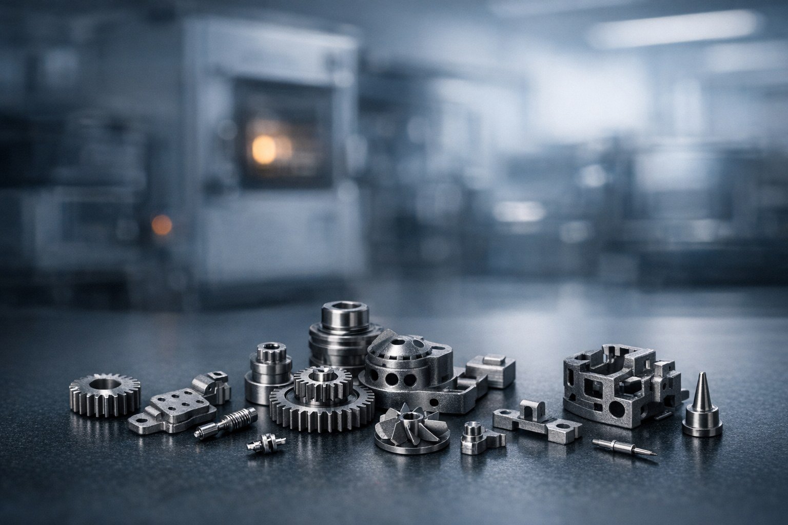
When is MIM a better choice than machining?

Usually when the part is small, complex, and intended for repeat production where tooling cost can be spread across volume.

Need Review Support for a MIM Program?

ELUFA MFG can review your drawing package, validate the route, and help you move from prototype assumptions to repeatable production.

ELUFA MFG

Shenzhen, Guangdong, China

Email: victor@elufamfg.com
Business Hours: Monday to Saturday, UTC+8

Quick Links

Home
Contact / RFQ
Prototype + Production Support
Engineering DFM Review
Quality Documentation on Request

© ELUFA MFG. All rights reserved.