Feasibility Review
Check geometry, tolerance realism, and annual demand before tooling decisions.
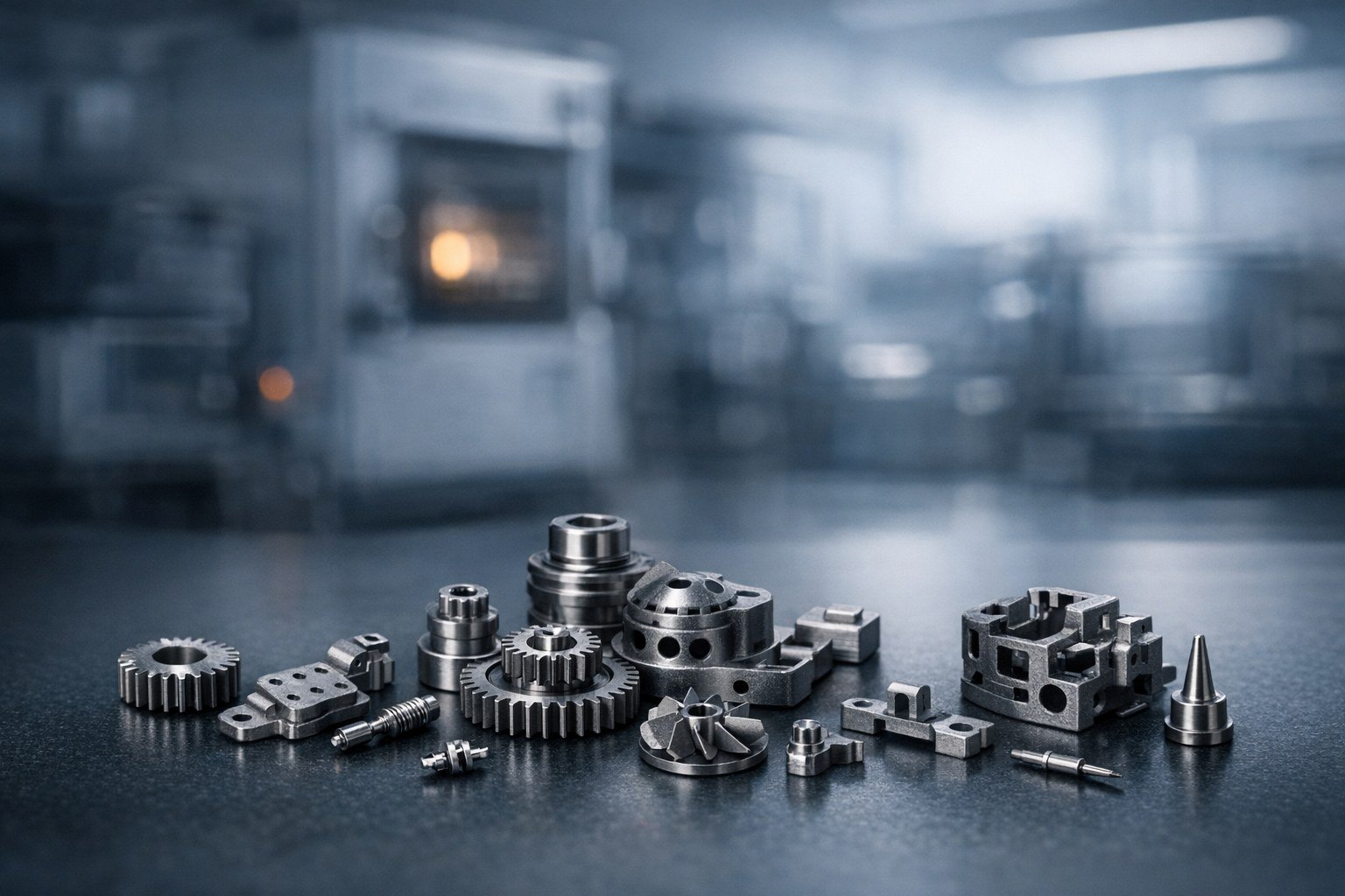
Metal Injection Molding
A practical route for small metal parts with dense geometry when conventional machining is too expensive and volume is high enough to support tooling logic.
Workflow
Tooling, molding, sintering, finish
Program fit
Complex small parts with scale potential
Review focus
Feasibility, shrink, secondary ops