ELUFA MFG

Sheet Metal Fabrication

Sheet Metal Fabrication for Enclosures, Brackets, Panels, and Formed Assemblies

Laser cutting, punching, forming, insertion, and assembly support coordinated as one process chain instead of isolated operations.
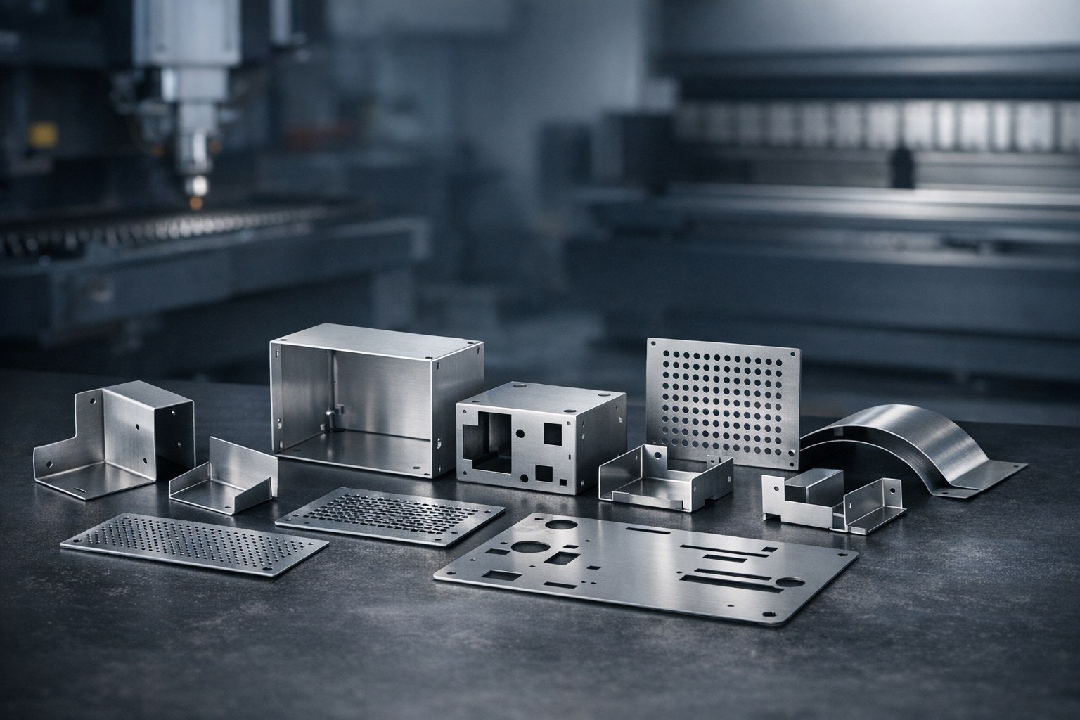
Sheet Metal Fabrication for Enclosures, Brackets, Panels, and Formed Assemblies

Workflow

Cut, punch, bend, assemble

Program fit

Prototype to volume production

Review focus

Flat pattern, bend logic, assembly fit

Sheet Metal Fabrication

Where Sheet Metal Fits Best

Sheet metal is the strongest fit when the part starts as flat stock and gains value through cutting, bend sequence, hardware insertion, and assembly integration. It works especially well for covers, cabinets, supports, guards, trays, and structural electronics hardware.

  • Panels, chassis elements, brackets, housings, and machine covers
  • Projects that need fast prototype validation before pilot or production release
  • Assemblies that combine formed parts, inserts, and light weld or join operations
  • Programs where finish appearance and fit consistency matter to downstream assembly

Program fit

This page is built to explain where the process belongs, what risks should be screened early, and how ELUFA approaches technical review before release.

Sheet Metal Fabrication

Sheet Metal Capability Focus

Laser Cutting

Profile generation for complex outlines, slots, and hole features with clean process control.

Punching

Repeat-feature efficiency for holes, louvers, and stamped details on suitable programs.

Forming

Press-brake strategies aligned to bend order, material thickness, and access constraints.

Assembly Support

Hardware insertion, weld coordination, and fabricated assembly readiness for release.

Process review

How We Reduce Sheet Metal Risk

Most sheet metal problems are upstream: flat-pattern assumptions, bend relief, hardware positioning, or assembly interfaces that were not resolved early enough. We look at the part as a process chain, not a single cut file.

Review goal

  • Check hole-to-edge spacing and formed-dimension realism against thickness and bend behavior
  • Review bend sequence so tooling access and downstream assembly remain practical
  • Separate cosmetic surfaces from functional join surfaces when finish requirements are different
  • Confirm insertion, tap, countersink, and weld expectations before prototype release

The objective is not to make the page sound technical. The objective is to make the RFQ and sample path more predictable.

Sheet Metal Fabrication

Sheet Metal Program Workflow

Step 01

Design review

Confirm flat pattern, bend intent, feature density, and assembly notes.

Step 02

Process setup

Finalize cutting, punching, forming, and insertion sequence.

Step 03

Pilot validation

Check fit, hardware location, formed dimensions, and finish condition.

Step 04

Production release

Run recurring lots with revision control and packaging discipline.

FAQ

Sheet Metal Fabrication FAQ

What helps quote sheet metal faster?

A clear drawing set with thickness, material, finish, and assembly notes reduces the back-and-forth immediately.

Can you handle prototype and production on the same project?

Yes. We structure the handoff so fit lessons from the prototype phase carry into recurring lots.

Do you only quote single flat parts?

No. We can review formed parts and fabricated assemblies when the join logic is provided.

Need Cut, Form, and Assembly Reviewed Together?

Send the drawings and quantity plan. We will return a sheet metal route built around the whole assembly, not just the flat pattern.

Start Sheet Metal RFQ