ELUFA MFG

CNC Machining

CNC Machining for Precision Metal and Engineering Plastic Parts

Milling and turning workflows built around datum control, practical tolerance strategy, and stable handoff from prototype to recurring supply.

CNC Machining for Precision Metal and Engineering Plastic Parts

Workflow

Milling + turning routes

Program fit

Prototype, pilot, repeat lots

Review focus

Critical dimensions and finishes

CNC Machining

Where CNC Adds the Most Value

CNC machining is the right process when geometry flexibility, dimensional control, and revision responsiveness matter more than dedicated forming-tool economics. We use it for housings, brackets, shafts, fixtures, mechanical interfaces, and mixed-feature parts that need reliable datums and clean engineering communication.

  • Complex pocket, bore, shoulder, slot, and interface geometry
  • Low-to-medium lot sizes or programs that still expect revision change
  • Parts that combine cosmetic surfaces with function-critical dimensions
  • Projects that may begin with prototypes and later stabilize into production lots

Program fit

This page is built to explain where the process belongs, what risks should be screened early, and how ELUFA approaches technical review before release.

CNC Machining

CNC Capability Focus

Milling Routes

3-axis and 4-axis strategies for pockets, faces, patterns, channels, and structural detail.
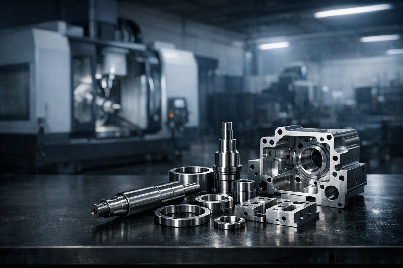
Turning Routes

OD, ID, groove, shoulder, and thread-critical components with concentric features.

Material Range

Aluminum, stainless, steel, brass, copper, and engineering plastics based on end use.

Secondary Finish Support

Anodizing, passivation, blasting, plating, marking, and assembly-prep finishing.

Process review

How We Reduce CNC Risk

The biggest CNC cost and lead-time problems usually come from overly dense tolerance stacks, difficult tool access, or cosmetic requirements that are not separated from true functional zones. We review the drawing with those issues in mind before release.

Review goal

  • Identify function-critical surfaces before assigning tight tolerances globally
  • Match internal corners and channel widths to realistic tooling access
  • Use a clear datum strategy so prototype inspection matches production setup logic
  • Flag features that may be better handled in a hybrid route or secondary operation

The objective is not to make the page sound technical. The objective is to make the RFQ and sample path more predictable.

CNC Machining

CNC Program Workflow

Step 01

Technical review

Confirm geometry, datum logic, tolerance concentration, and finish expectations.

Step 02

Route planning

Select milling, turning, or hybrid workflow with inspection checkpoints.

Step 03

Sample approval

Verify first-off parts against drawing-critical dimensions before lot release.

Step 04

Controlled production

Run lots with revision discipline and agreed quality outputs.

FAQ

CNC Machining FAQ

What files are best for CNC RFQ?

A 3D model plus a 2D drawing with revision, critical dimensions, and finish requirements gives the cleanest start.

Should every tolerance be tight?

No. Tight tolerances should be concentrated on true functional interfaces so cost and process risk stay under control.

Can one part use both milling and turning?

Yes. We regularly recommend hybrid routes when rotational and non-rotational features exist on the same part.

Need Milling and Turning Reviewed in One Quote?

Send the drawing package and demand range. We will return a practical machining route and RFQ response.

Request CNC Review